01 · Speed
Fast and precise.
Uncompromised speed and accuracy simultaneously, no tradeoff needed. Achieve micron-level precision in industrial 3D printing.
2m/s
·
Peak velocity
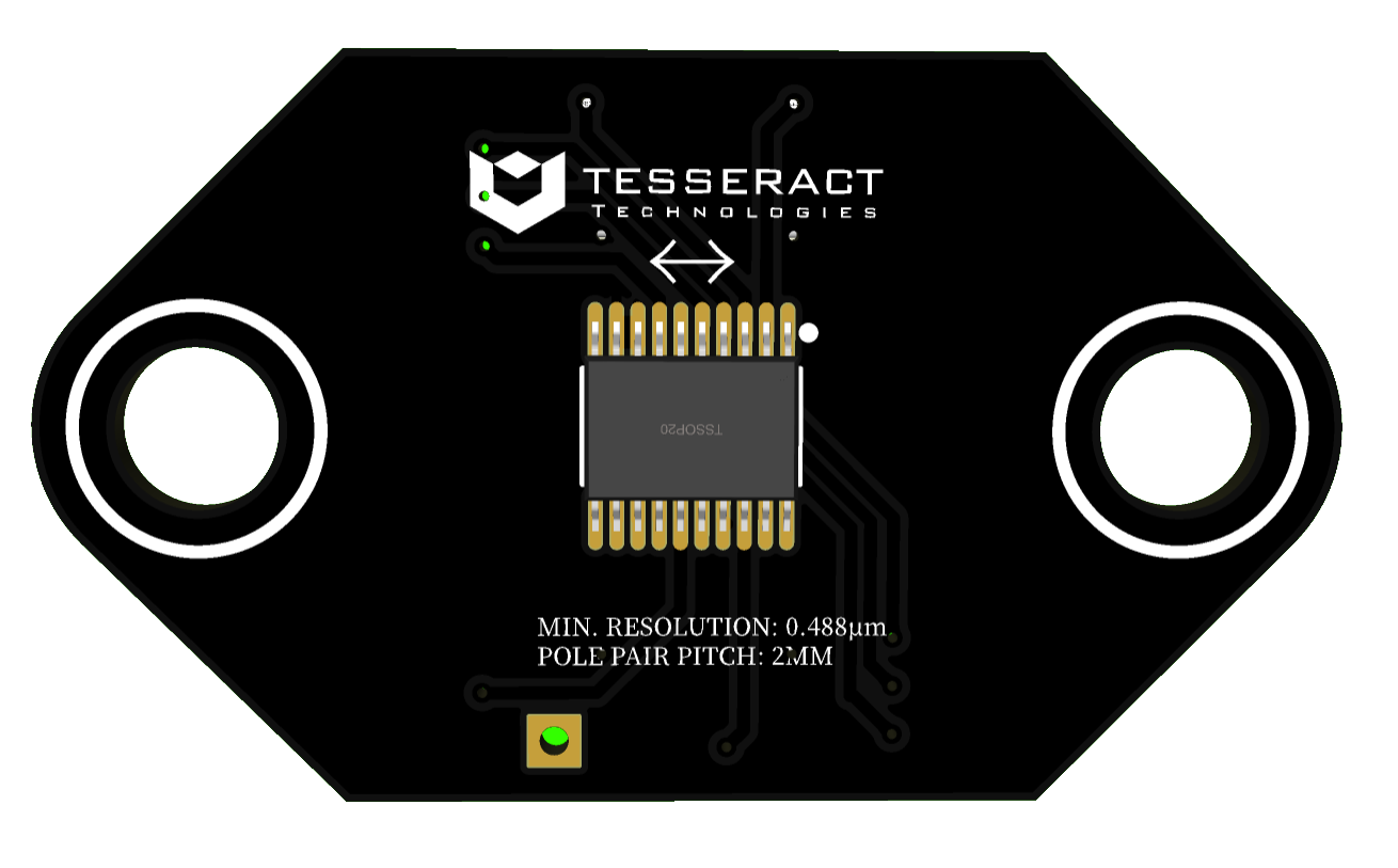
0.5µm
Resolution
We help you build the next generation industrial 3D printers and other machines.
Uncompromised speed and accuracy simultaneously, no tradeoff needed. Achieve micron-level precision in industrial 3D printing.
Self-correcting motor system detects and adjusts deviations in real time, drastically reducing print failures and improving reliability.
Live data measurements allow you to analyze motor data and observe how parameter adjustments influence performance.
No mechanical contact means no wear and virtually no maintenance, maximizing uptime in industrial environments.
The configurations are endless. Stators are made‑to‑measure to the millimeter, so every axis fits your machine — not the other way around.
…you want the advantages of linear motors such as direct drive, zero backlash, closed‑loop precision but don't need sub‑nanometer accuracy.
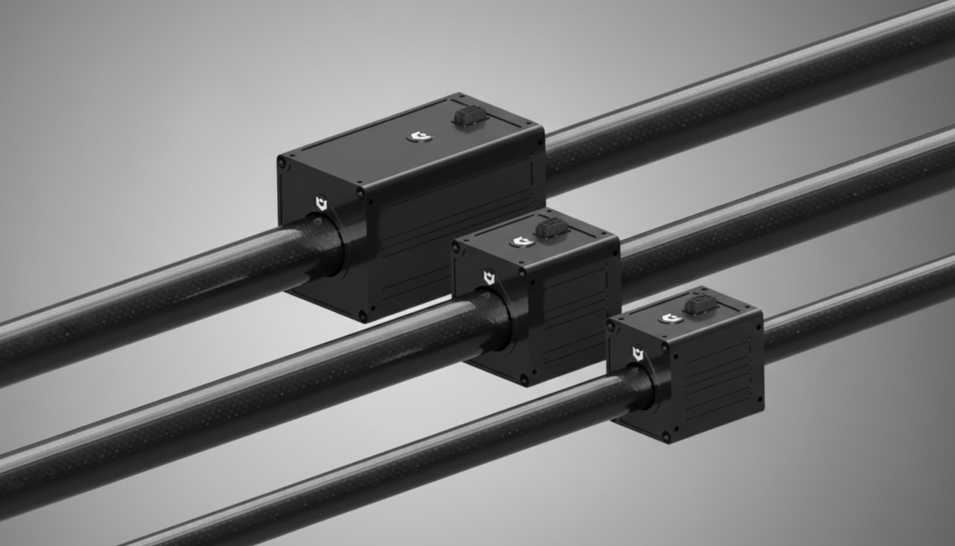
A linear motor is a servo motor that has been "unrolled". Where a rotary motor produces torque on a shaft, a linear motor produces force directly along a straight line. No belts, no pulleys, no leadscrews in between.
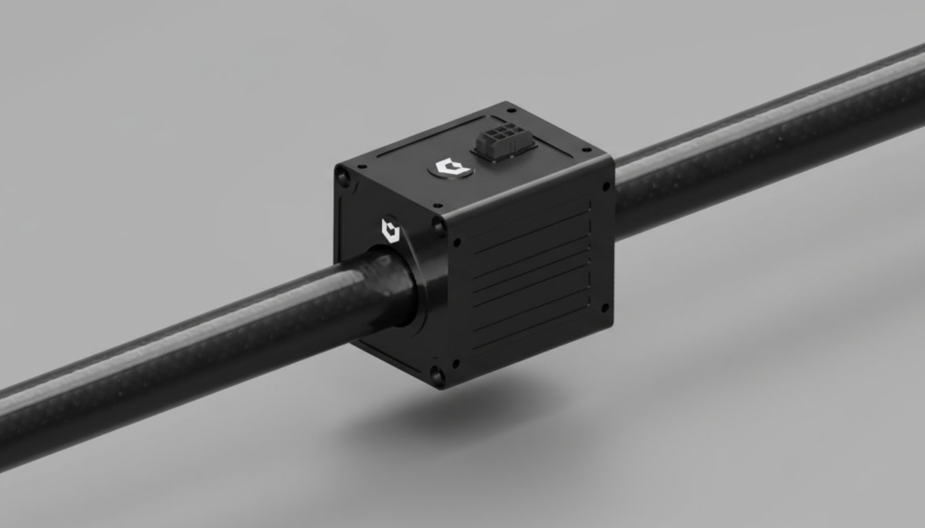
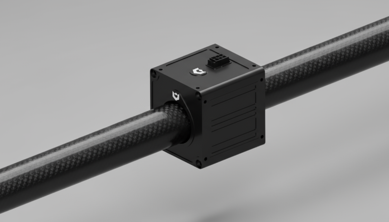
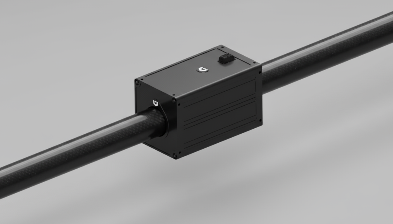
It has two parts. A stator (a track of permanent magnets)and a forcer (the moving part with the coils). Energising the coils creates a magnetic field that pushes the forcer along the stator. The motion is direct, frictionless, and has no wear parts.
Each axis we deliver is a tuned bundle: the motor moves, the encoder reports, the controlboard closes the loop. Below, a deep-dive into each — what's inside, what it does, and how it slots into your machine.
Our motors are ironless: the forcer has no iron core, which means zero cogging and a perfectly smooth force profile across the stator. Magnets sit in the stator track; coils sit in the forcer; the air gap between them is 1 mm.
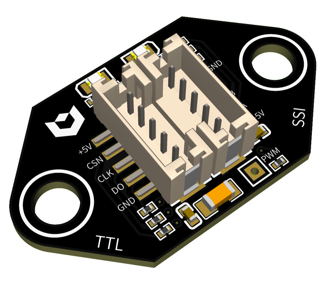
An optical linear encoder sits parallel to the stator. The read‑head on the forcer reports incremental position to the controlboard at 5,000 Hz. Sub‑micron resolution means the control loop can correct disturbances long before they become visible motion errors.
The encoder is factory‑aligned and shipped as part of the motorbundle. No optical setup, no zeroing procedure on install — power on, home once, run.
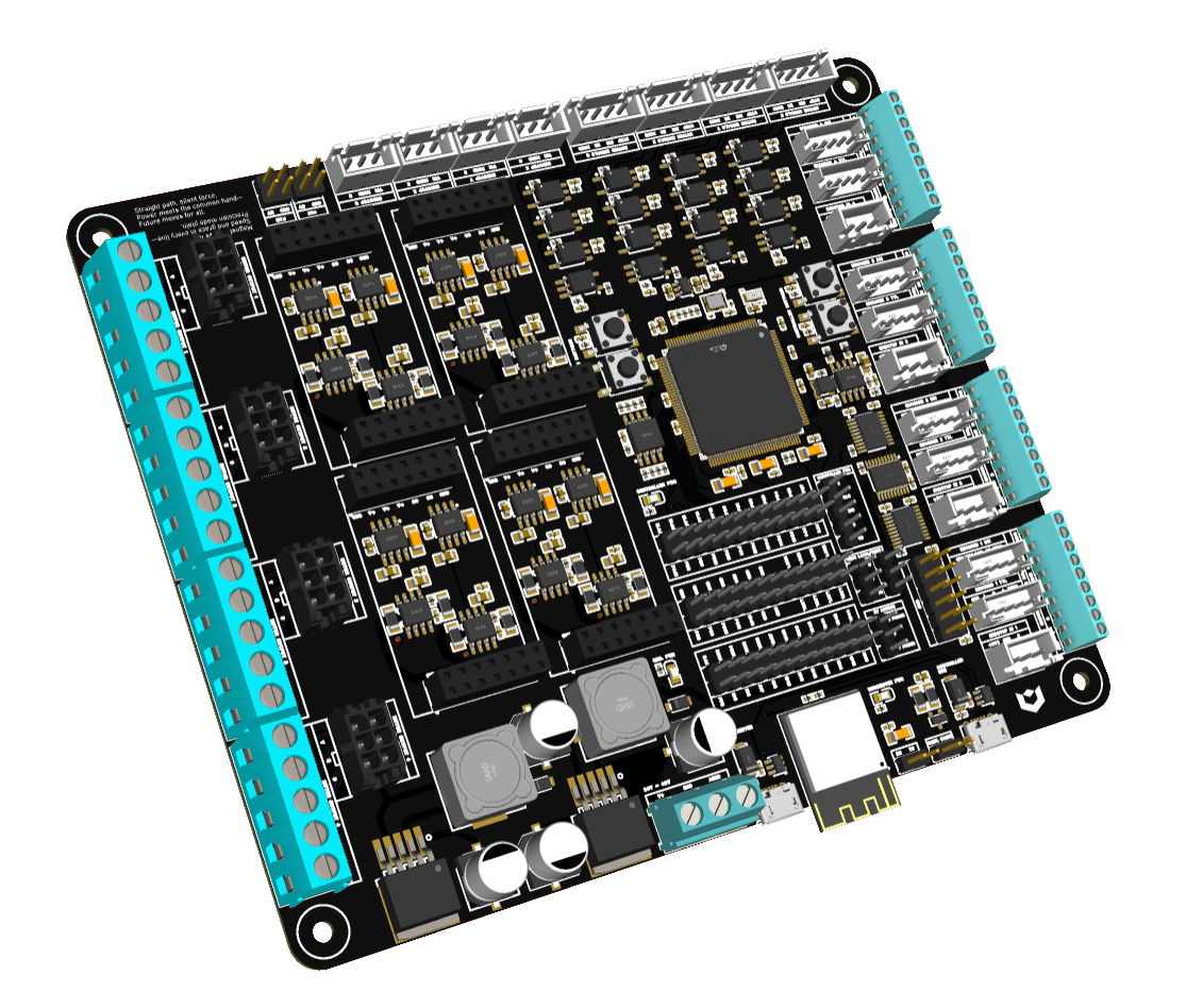
Lotus drives up to four motors per board with a 5 kHz current loop. It runs a built‑in webserver, so configuring an axis happens in any browser.
We deliver motorbundles: the linear motors (forcer + stator), encoders, and control boards. Everything outside stays on your side.
Tuned, tested and shipped as one system.
The frame and mechanics around the motor are yours to spec.
Stators are made‑to‑measure to the millimeter; force values are at the rated bus voltage with passive cooling unless noted.
| Specification |
 |
 |
 |
|---|---|---|---|
| Force | |||
| Continuous force Fcont @ 500 mm/s | 20N | 35N | 70N |
| Motor constant per phase | ±2.45N/A | ±4.10N/A | ±6.30N/A |
| Motor constant overall | ±7.35N/A | ±12.30N/A | ±18.90N/A |
| Motion & encoder | |||
| Absolute max speed SSI · quadrature | 2m/s · 0.5m/s | ||
| Encoder resolution Tesseract encoder | 0.5µm SSI · 2 / 4 / 8µm quadrature | ||
| Encoder strip size | 10 × 1.5mm | ||
| Accuracy ± 15 m/s² @ 0.5 m/s | < 50µm | ||
| Geometry | |||
| Max stator length made‑to‑measure | 1200mm | 1700mm | 1700mm |
| Stator outer diameter | Ø 20mm | Ø 28mm | Ø 28mm |
| Forcer inner diameter | Ø 22mm | Ø 30mm | Ø 30mm |
| Forcer size H × W × L | 49 × 44 × 55.5mm | 57 × 52 × 55.5mm | 65 × 60 × 106.5mm |
| Magnet pitch N–N | 51mm | ||
| Electrical | |||
| Rated current* Irated | 2.7A | 2.9A | 3.7A |
| Power consumption at rated Fcont | ±34W | ±47.5W | ±80W |
| Connectors, cabling & environment | |||
| Forcer / encoder connectors | MOLEX Microfit 3.0 | ||
| Cabling | Forcer 18 AWG · Encoder 26 AWG · 5‑core shielded | ||
| Maximum ambient temperature | 40°C | ||
Share what you're building and we'll come back with specs, a CAD model, and honest advice on whether we're a fit.